

How do I connect a BARANI FARS reed-switch fan-speed output to a Campbell Scientific CR1000X data logger?
/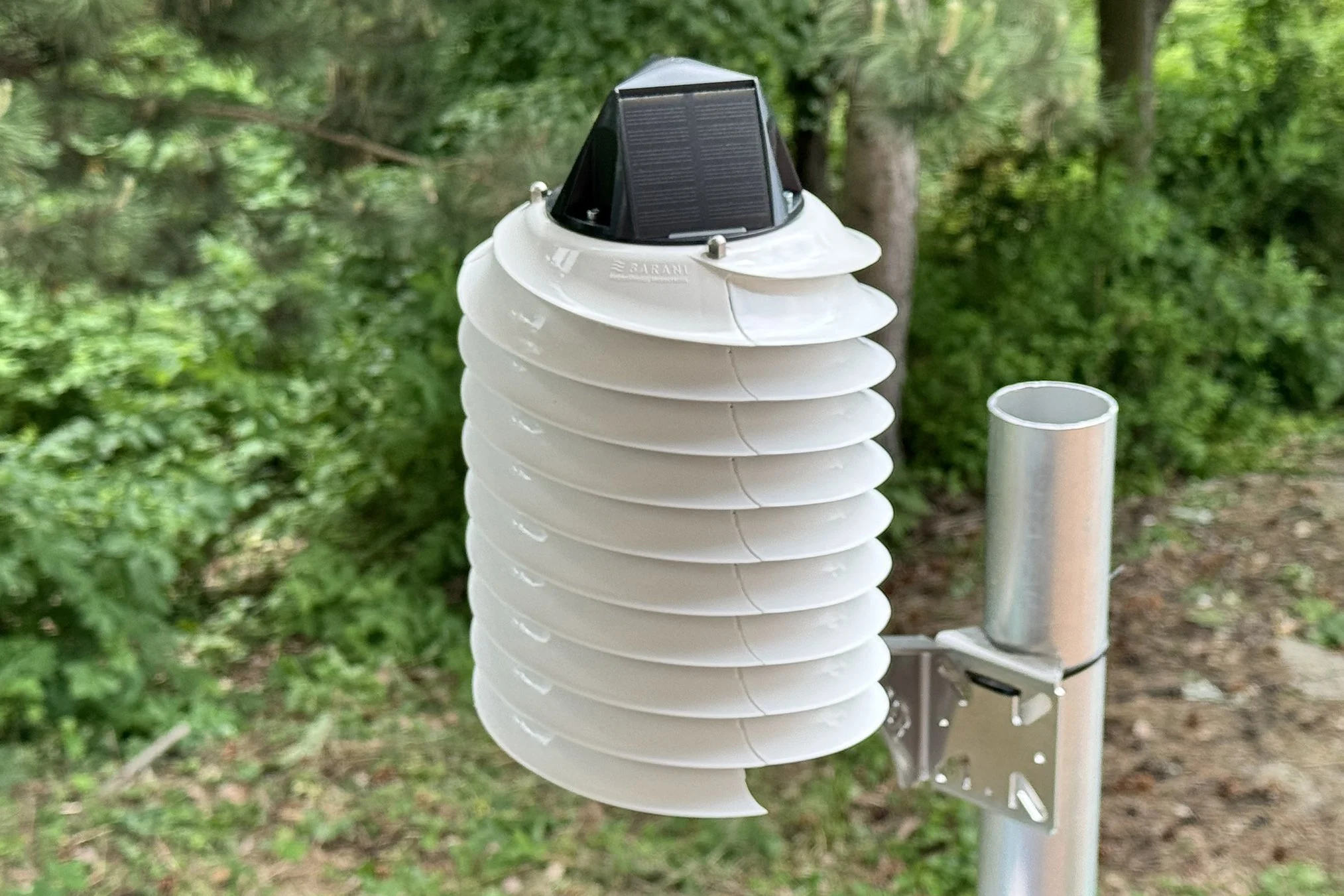
Fan Aspirated Radiation Shield (FARS) - FARS MeteoShield Pro
QUESTION: What signal does the BARANI FARS fan-speed cable provide?
ANSWER: The FARS MeteoShield Pro provides a two-wire, polarity-independent, normally-open reed-switch output. A magnet on the rotating fan closes the contact once during every revolution.
According to the FARS MeteoShield Pro data sheet :
- The output is one pulse per revolution.
- 1 Hz corresponds to 60 rpm.
- The contact is normally open.
- The contact is in series with an internal 24 Ω resistor.
- The normal fan-speed range is approximately 0–2500 rpm.
- The stated maximum output speed is 2600 rpm.
Because the FARS produces one pulse per revolution, its conversion simplifies to:
QUESTION: Is the reed contact open or closed when no magnet is present?
ANSWER: It is open when the magnet is absent and closes while the rotating magnet passes through the reed switch's actuation field.
When connected between an SDM-IO16 input and ground:
- An open contact is read as logic state
1. - A closed contact is read as logic state
0.
Campbell command 92, included in the diagnostic portion
of the program below, reads the present state of all 16 SDM-IO16 inputs
into 16 separate variables. This is useful for a stationary test: stop
the fan, hold the magnet over the reed switch, and confirm that the
indicated state changes from 1 to 0.
QUESTION: How should the two FARS output wires be connected?
ANSWER: For the example program, connect the FARS output to SDM-IO16 port 1:
- Connect either FARS output lead to SDM-IO16 input 1.
- Connect the other FARS output lead to an SDM-IO16 G terminal.
- Set the SDM-IO16 hardware address to 1, matching the program.
The two FARS leads have no polarity. Do not apply a separate excitation voltage to the FARS cable when using the SDM-IO16 internal pull-up.
QUESTION: Does the Campbell program calculate speed from duty cycle?
ANSWER:
No. Campbell SDMIO16 commands 24 through 46
measure frequency. Duty-cycle measurements use commands
47 through 69.
The original instruction:
SDMIO16(Freq(),Ret_Code_1,1,46,0,0,0,0,30,0)
does measure frequency, but the final 30 multiplies every
measured frequency by 30. It is not a duty-cycle setting.
A multiplier of 30 is correct for a conventional fan tachometer that produces two pulses per revolution:
The FARS produces only one pulse per revolution, so its correct multiplier is 60:
| Program item | Original sample | Correct FARS treatment |
|---|---|---|
| Measurement method | Frequency, command 46 |
Frequency; retain command 46 or use command 24 for port 1 only |
| Pulses per revolution | Effectively assumes 2 | 1 pulse per revolution |
| Frequency multiplier | 30 |
Read raw Hz with 1.0, then multiply the FARS channel by 60.0 |
| Input mode | 2, no debounce |
Retained intentionally for the narrow FARS pulse |
| Destination name | Freq(), although already scaled by 30 |
Store true Hz in FARS_Hz and calculated speed in FARS_RPM |
QUESTION: What debounce setting should be used for the Standex-Meder MK24 reed contact?
ANSWER: On the original SDM-IO16, begin with mode 2—digital input with no debounce filter.
The MK24 series data sheet specifies a maximum operating time of 0.25 ms including bounce and a maximum release time of 0.15 ms. The 0.25 ms value is not a separately specified bounce-only duration, and it is not the contact-closed pulse width of the assembled FARS.
In the assembled FARS, the available contact-closed pulse duration depends on the complete magnetic geometry:
- magnet length and strength;
- magnet-to-switch air gap;
- reed-switch sensitivity and orientation;
- fan radius and rotational speed; and
- the time for which the contact remains inside the magnetic actuation field.
Campbell's default switch-closure mode 3 requires the
input to remain closed for approximately 3.17 ms and then open for
approximately 3.17 ms. That filter is far longer than an assumed
1.00% contact-closed pulse at 2500–3000 rpm.
| Campbell input configuration | Sampling interval | Minimum clean state without filtering | Default mode-3 debounce |
|---|---|---|---|
| Original SDM-IO16 | 0.244 ms at 4096 Hz | 0.244 ms | Approximately 3.17 ms |
| SDM-IO16A, low-speed mode | 0.244 ms at 4096 Hz | 0.244 ms | Approximately 3.17 ms |
| SDM-IO16A, high-speed mode | 0.06104 ms at 16,384 Hz | 0.06104 ms | Approximately 0.7925 ms |
For the original SDM-IO16, the smallest nonzero programmable debounce parameter gives a clean-state recognition time of:
A 0.488 ms filter would reject an exactly 1.00% contact-closed pulse at 2500 rpm, because that pulse lasts only 0.240 ms.
QUESTION: Can the original SDM-IO16 reliably detect the short FARS reed-switch pulse at high fan speed?
ANSWER: It depends on the actual duration of the brief contact-closed pulse. The program measures frequency, not duty cycle, but the LOW pulse created when the reed contact closes must still remain long enough for the SDM-IO16 input sampler to detect it.
The original SDM-IO16 samples each input 4096 times per second. The time between samples is:
Campbell specifies that an input must remain HIGH or LOW for at least approximately 0.244 ms for a state change or pulse to be counted. Campbell's detailed appendix states the conservative guarantee as longer than the interval between samples.
The FARS reed contact is normally open. It closes briefly as the rotating magnet passes the switch, pulling the SDM-IO16 input LOW. Therefore, the important quantity is the contact-closed LOW-pulse width, not a duty-cycle measurement.
The period of one fan revolution is:
At an exactly 1.00% contact-closed fraction:
| Fan speed | Pulse frequency | Revolution period | Closed pulse at exactly 1.00% | Original SDM-IO16 requirement | Guaranteed? |
|---|---|---|---|---|---|
| 2500 rpm | 41.667 Hz | 24.000 ms | 0.240 ms | At least approximately 0.244 ms | No |
| 2600 rpm | 43.333 Hz | 23.077 ms | 0.231 ms | At least approximately 0.244 ms | No |
| 3000 rpm | 50.000 Hz | 20.000 ms | 0.200 ms | At least approximately 0.244 ms | No |
At 2500 rpm, one revolution lasts 24.000 ms. One percent of 24.000 ms is 0.240 ms. This is approximately 0.004 ms shorter than the SDM-IO16's nominal 0.244 ms minimum.
At 3000 rpm, one revolution lasts 20.000 ms. One percent of 20.000 ms is 0.200 ms, which is approximately 0.044 ms shorter than the nominal minimum.
| Fan speed | Contact-closed fraction required for guaranteed detection |
|---|---|
| 2500 rpm | More than 1.017% |
| 2600 rpm | More than 1.058% |
| 3000 rpm | More than 1.221% |
At an exactly 1.00% contact-closed fraction, the theoretical sampling boundary is 40.96 Hz, equivalent to 2457.6 rpm. Therefore, an exactly 1.00% or shorter pulse is outside the original SDM-IO16's guaranteed detection range at 2500 rpm, 2600 rpm, and 3000 rpm.
Measure the actual LOW-pulse width at the SDM-IO16 input with an oscilloscope while the FARS is operating near maximum speed. If the pulse is shorter than 0.244 ms, use an SDM-IO16A in high-speed mode or an external monostable pulse stretcher that produces a clean, longer output pulse.
QUESTION: What CRBasic program should be used with a CR1000X and an original SDM-IO16?
ANSWER: The following focused program assumes:
- CR1000X data logger;
- SDM-IO16 address
1; - FARS output connected to SDM-IO16 port
1; - one pulse per revolution; and
- a one-second measurement update.
It configures only port 1 as an unfiltered digital input, leaving ports 2–16 unchanged.
'CR1000X + Campbell Scientific SDM-IO16
'BARANI FARS fan-speed reed output
'
'Wiring:
'  Either FARS lead -> SDM-IO16 port 1
'  Other FARS lead  -> SDM-IO16 G
'
'SDM address: 1
'FARS output: 1 pulse per revolution
'Measurement method: frequency, not duty cycle

Const FARS_PULSES_PER_REV = 1
Const FARS_TEST_CEILING_RPM = 3000

Public FARS_Hz
Public FARS_RPM
Public FARS_Overrange

Public IO16_State(16)

Public Ret_Setup
Public Ret_Frequency
Public Ret_State

BeginProg

  'Configure SDM-IO16 port 1 only.
  '
  'Command 89 configures ports 4 through 1.
  'Mode digits are ordered as port 4, port 3, port 2, port 1.
  '
  '9992 means:
  '  Port 4 = 9, no change
  '  Port 3 = 9, no change
  '  Port 2 = 9, no change
  '  Port 1 = 2, digital input with no debounce
  '
  'Perform setup during two startup scans.

  Scan(1,Sec,0,2)

    SDMIO16(Null,Ret_Setup,1,89,0,0,0,9992,1.0,0)

  NextScan


  'Continuous measurement scan.

  Scan(1,Sec,0,0)

    'Command 24 reads frequency from SDM-IO16 port 1.
    '
    'Multiplier = 1.0:
    'Store the actual raw frequency in Hz.
    '
    'Offset = 0:
    'No value is added to the measurement.

    SDMIO16(FARS_Hz,Ret_Frequency,1,24,0,0,0,0,1.0,0)


    'FARS provides one pulse per revolution.
    '
    'RPM = Hz x 60 / pulses per revolution

    FARS_RPM = FARS_Hz * 60.0 / FARS_PULSES_PER_REV


    '3000 rpm is a program diagnostic ceiling and test margin.
    'The published FARS maximum operating speed is 2600 rpm.
    '
    'Preserve the measured value so bounce spikes remain visible.

    If FARS_RPM > FARS_TEST_CEILING_RPM Then
      FARS_Overrange = 1
    Else
      FARS_Overrange = 0
    EndIf


    'Diagnostic input-state reading.
    '
    'With the fan stopped:
    '  IO16_State(1) = 1 when the reed contact is open.
    '  IO16_State(1) = 0 when a magnet closes the contact.
    '
    'Do not use this once-per-second state value to evaluate
    'the pulse waveform while the fan is rotating.

    SDMIO16(IO16_State(),Ret_State,1,92,0,0,0,0,1.0,0)


    'Add FARS_Hz, FARS_RPM, FARS_Overrange,
    'Ret_Frequency and any desired diagnostic variables
    'to the project's existing DataTable.

  NextScan

EndProg24 reads only port 1 and stores one result.
Command 46 reads all 16 ports and requires a 16-element
destination array. Either is valid; command 24 makes the single-FARS
example easier to understand and does not change the other channels.
Compile the program in Campbell Scientific CRBasic Editor for the operating-system version installed in the CR1000X before deployment.
QUESTION: What does each SDMIO16 parameter mean?
ANSWER: Campbell defines the instruction as:
SDMIO16(Dest, IO16Status, SDMAddress, IO16Cmd,
        Mode16_13, Mode12_9, Mode8_5, Mode4_1,
Multiplier, Offset)| Parameter | Value in this program | Meaning |
|---|---|---|
Dest |
FARS_Hz |
Variable receiving the measured port-1 frequency |
IO16Status |
Ret_Frequency |
Communication result; zero indicates a successful SDM command |
SDMAddress |
1 |
Hardware address selected on the SDM-IO16 |
IO16Cmd |
24 |
Read frequency from port 1 |
Mode16_13 through Mode4_1 |
0,0,0,0 |
Ignored for frequency command 24; enter zero |
Multiplier |
1.0 |
Preserves the result as true frequency in Hz |
Offset |
0 |
Adds nothing to the measured frequency |
Campbell's complete instruction reference is available in the SDMIO16 CRBasic documentation .
QUESTION: What is the smallest change to the original all-port sample?
ANSWER: Read all channels as unscaled frequency in Hz, then apply the appropriate pulses-per-revolution conversion separately to each sensor.
Public Frequency_Hz(16)
Public FARS_RPM

'Keep the existing no-debounce setup.
SDMIO16(Null,Ret_Code,1,90,2222,2222,2222,2222,1.0,0)

'Read all 16 channels as actual frequency in Hz.
'The multiplier is 1.0, not 30.
SDMIO16(Frequency_Hz(),Ret_Code_1,1,46,0,0,0,0,1.0,0)

'Example: FARS connected to port 1.
'FARS has one pulse per revolution.
FARS_RPM = Frequency_Hz(1) * 60.0
Other fan tachometer channels that produce two pulses per revolution can still be converted with a multiplier of 30:
Conventional_Fan_RPM = Frequency_Hz(2) * 30.0QUESTION: What should be changed when an SDM-IO16A is installed?
ANSWER:
The SDM-IO16A supports command 104, which enables a
16,384 Hz high-speed sampling mode. Execute this command during every
scan, before reading the frequency.
'Declare with the other public variables:
Public Ret_HighSpeed

'Only for an SDM-IO16A.
'Place inside every measurement scan before command 24 or 46.

SDMIO16(Null,Ret_HighSpeed,1,104,0,0,0,0,1.0,0)
In high-speed mode, an unfiltered state needs to last approximately 0.06104 ms rather than 0.244 ms. A clean 0.200 ms pulse at 3000 rpm is therefore longer than the high-speed sampling requirement.
See the Campbell Scientific SDM-IO16A manual for the high-speed command and timing specifications.
QUESTION: How can a reed-switch, wiring, pulse-width, or scaling problem be distinguished?
ANSWER: Use the following symptoms as a diagnostic guide:
| Observed result | Most likely explanation | Recommended check |
|---|---|---|
| Displayed speed is exactly one-half of the expected value | The program uses multiplier 30, which assumes two pulses per revolution | Read raw Hz and multiply the FARS channel by 60 |
| Correct reading at moderate speed, but zero or intermittent near maximum speed | The closed pulse may be shorter than the original SDM-IO16's 0.244 ms sampling interval | Measure pulse width at the IO16 terminal with an oscilloscope |
| RPM occasionally jumps above the physical fan-speed limit | Contact bounce, cable interference, or multiple transitions are being counted | Inspect the waveform; use an appropriate pulse-conditioning circuit if necessary |
IO16_State(1) remains 1 with a stationary magnet directly over the switch |
Contact is not closing, magnet position or orientation is incorrect, or wiring is open | Test continuity directly at the FARS cable and then at the IO16 terminal |
IO16_State(1) remains 0 with the magnet removed |
Short circuit, stuck contact, or continuous magnetic actuation | Disconnect the FARS cable and compare the port state |
Ret_Frequency or another return code is nonzero |
SDM communication, address, power, or cable problem | Verify the hardware address, 12 V supply, ground, and SDM-C1/C2/C3 wiring |
| Frequency remains zero only at very low speed | The frequency command has received fewer than two complete high-to-low transitions during the measurement interval | Increase the interval if low-speed measurement is required |
With a one-second frequency measurement interval and one pulse per revolution, the SDM-IO16 reports 0 Hz when fewer than two high-to-low transitions occur between reads. This can affect readings below about 120 rpm while the fan is starting or stopping, but it is not relevant near the normal operating speed.
QUESTION: What is the final recommended configuration?
ANSWER:
- Measure frequency, not duty cycle.
- Use 60 rpm per hertz because the FARS has one pulse per revolution.
- Use SDM-IO16 input mode 2 with no internal debounce as the initial configuration.
- Do not use the default 3.17 ms switch-closure filter for an expected narrow perimeter pulse.
- Confirm that the stationary input changes from 1 to 0 when the magnet operates the reed contact.
- Measure the dynamic contact-closed pulse width near 2500–2600 rpm if the original SDM-IO16 misses pulses.
- Use an SDM-IO16A in high-speed mode or a defined-width external pulse conditioner when the pulse is shorter than 0.244 ms.
- Treat RPM spikes above the physical limit as possible contact bounce or electrical noise rather than valid fan speed.